

 Current position > News detail
『Hydraulic Oil Flow Meter DN80 System Balancing and Pressure Drop』Related information(flow rotameter|digital flow meter|balo meter|hydraulic flow meter|volumetric meter|positive displacement meter|pitot tube flow meter|displacement meter|cfm meter|variable area flow meter|inline flow meter|differential pressure flow meter|calibrated flow meter|velocity meter|paddle wheel flow meter|oval gear flow meter|anemometer hvac|multiphase flow meter|doppler flow meter|thorpe tube flowmeter|heat flow meter)
Hydraulic Oil Flow Meter DN80: System Balancing and Pressure Drop in Practice
Quick Answer
In hydraulic power units, a DN80 flow meter installed in the wrong location or with poor pipe matching creates permanent pressure drop that steals 5% to 15% of your pump output. You balance the system by placing the meter where flow is fully developed and straight pipe runs are long enough. For a DN80 line running ISO VG 46 hydraulic oil at 40 °C and 8 bar, expect 0.08 bar to 0.25 bar pressure drop across a full bore electromagnetic meter, depending on liner and electrode design. Send us your oil viscosity at operating temperature, pipe schedule, and flow range. We will recommend a meter that keeps your system balanced without throttling your pump.
Why Hydraulic Oil Systems Struggle With Flow Metering
Most hydraulic power units and test benches use flow meters as a diagnostic tool, not just a totalizer. Engineers want to catch pump wear early. They want to spot internal leakage in cylinders before a machine goes down. The problem is that many flow meters add permanent pressure loss. A gear meter with tight clearances on a DN80 line running cold oil in the morning can choke flow and trip the bypass valve. We have seen this on customer sites many times. The operator blames the pump. The real issue is the meter selection and where it sits in the circuit.
Here is the thing about hydraulic oil. Viscosity changes fast with temperature. A system that runs ISO VG 46 at 50 °C behaves very differently during a cold start at 10 °C. At low temperature the oil is thicker. A positive displacement meter sees higher mechanical resistance. A turbine meter spins slower. A Coriolis meter still measures mass flow correctly, but the pressure drop goes up because viscosity dampens the tube vibration. You need a meter type that fits the viscosity range and does not punish the system with excessive pressure loss when the oil is cold.
System balancing means matching the meter choice to the hydraulic circuit, not forcing the circuit to adapt to the meter. A DN80 line in a large press or injection molding machine often runs 200 to 500 L/min. If you install a meter with a reduced bore or internal obstructions, you create a bottleneck. The pump compensates by raising pressure. Energy turns into heat. Oil life shortens. The maintenance team sees higher fluid temperatures and assumes the cooler is undersized. The root cause is a meter with too small a flow path or too high a pressure drop across its measuring element.
DN80 Line Sizing and Pressure Drop Realities
A full bore electromagnetic flow meter on a DN80 schedule 40 pipe has the same internal diameter as the pipe itself. No reduction. No moving parts. A customer in Malaysia running a hydraulic test stand for remanufactured excavator pumps confirmed this with before and after pressure readings. He replaced an older positive displacement meter with a Silver Instruments electromagnetic flow meter DN80 with hard rubber liner and 316L electrodes. The line pressure at 400 L/min with ISO VG 68 oil at 45 °C dropped by 0.15 bar. That is small enough to ignore in system balancing calculations. The previous meter ate 0.6 bar. Over a 16 hour shift, that 0.45 bar difference saved real power cost on a 55 kW pump motor.
But electromagnetic meters have limits. The oil must have a minimum conductivity. Pure hydraulic oil does not conduct. That is why Silver Instruments builds electromagnetic flow meters with a special capacitive electrode design for low conductivity fluids down to 0.05 µS/cm. Standard magmeters need 5 µS/cm minimum. Hydraulic oil with some additive packages or slight water content can reach 0.1 to 0.5 µS/cm. Test the oil conductivity first. If the oil is bone dry and non conductive, you switch to a different technology. An oval gear meter with PEEK gears and hardened bearings works on pure oil and handles viscosity from 1 to 100,000 cP. But that gear meter brings back the pressure drop question. On DN80 lines with high flow, the gear meter body is physically smaller than the pipe and requires reducers. Reducers add pressure loss. You must calculate the total system pressure drop including the reducers, not just the meter itself.
Where to Place the DN80 Meter for Accurate System Balancing
Most engineers skip this part and bolt the meter wherever there is physical space. Bad idea. A flow meter needs fully developed flow. That means 5 to 10 pipe diameters of straight run upstream and 2 to 3 diameters downstream. For DN80 pipe that is 400 mm to 800 mm upstream and 160 mm to 240 mm downstream. Install the meter after a 90 degree elbow with no straight run and the velocity profile is distorted. The meter reads 3% to 8% high or low depending on the bend direction relative to the electrodes. System balancing becomes guesswork. In a hydraulic power unit return line, place the meter downstream of the return filter and upstream of the cooler if possible. The oil temperature is stable there. Viscosity is predictable. Flow is less turbulent than directly after the pump. A paint manufacturer in Sout
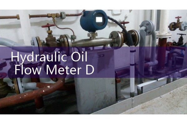
For pump test stands, put the meter on the pump discharge line before the directional control valve. This measures actual pump output under load. You compare this reading against the pump nameplate displacement and shaft speed. Any deviation tells you about volumetric efficiency. A DN80 electromagnetic flow meter with pulse output into a Silver Instruments paperless recorder gives you a real time trend. You see pump degradation over weeks, not suddenly at failure. That is system balancing with data, not belief.
Common DN80 Hydraulic Oil Flow Meter Options and Their Pressure Drop
Silver Instruments offers four meter types suitable for DN80 hydraulic oil lines. Each has a different pressure drop profile. The full bore electromagnetic flow meter causes almost zero permanent pressure loss. It is the top choice for low pressure return lines and test stands where you cannot afford added pump load. The oval gear flow meter in 316L body with PEEK rotors handles wide viscosity swings and gives direct volumetric reading without needing conductivity. Its pressure drop at 400 L/min with ISO VG 46 at 40 °C is roughly 0.3 bar to 0.5 bar depending on the meter housing size and bearing type. This is acceptable for many systems but must be included in total system head loss calculations. A turbine flow meter on DN80 with tungsten carbide bearings works well on clean, medium viscosity oil and pressure drop is around 0.15 bar at midrange flow. It is sensitive to pulsating flow from piston pumps, so install a dampener or use a Coriolis meter instead. The Coriolis mass flow meter measures directly in kg/h, independent of viscosity, temperature, or density. Pressure drop across a DN80 Coriolis meter tube at 400 L/min with ISO VG 46 is typically 0.2 bar to 0.6 bar. Higher than electromagnetic, but you get mass flow, density, and temperature from one device. A hydraulic oil blending plant in the Middle East uses this setup to batch additives by mass, not volume, because mass does not change with temperature.
Pressure Drop Budgeting Before Installation
Before ordering a DN80 meter, calculate the pressure drop budget for the entire hydraulic circuit. A typical industrial hydraulic system operates between 100 bar and 350 bar working pressure. Return lines are much lower, from 2 bar to 10 bar. Losing 0.5 bar in the return line meter is usually fine. Losing 0.5 bar in a charge pump suction line starves the main pump and causes cavitation. That is a costly mistake. A customer in Vietnam learned this the hard way on a hydraulic press rebuild. They installed an oval gear meter on the suction side of a piston pump. The meter added 0.4 bar restriction. The pump whined and failed within three weeks. We helped them relocate the meter to the case drain line where flow is lower and backpressure is acceptable. Problem solved.
So how do you calculate the total pressure drop including the meter? Add the meter manufacturer’s stated pressure drop at your maximum flow and operating viscosity to the piping losses. For turbulent flow in DN80 schedule 40 pipe at 400 L/min with ISO VG 46, piping friction loss is roughly 0.02 bar per meter of straight pipe. Add 0.1 bar per 90 degree elbow. Add 0.05 bar for a fully open ball valve. Then add the meter pressure drop. If the total exceeds your allowable return line backpressure or suction line vacuum budget, upsize the meter or choose a lower restriction type. This is basic hydraulic engineering that gets skipped when the project is rushed.
Real Field Adjustments for Temperature and Viscosity
Hydraulic oil viscosity changes with temperature and shear. A meter calibrated at 40 °C with ISO VG 32 will read differently when the oil hits 60 °C after two hours of operation. Oval gear meters compensate somewhat because they measure discrete volumes. However, internal leakage past the gears increases as viscosity drops. At 60 °C and low viscosity, the meter under registers by 0.5% to 1.5% because some fluid slips past without being counted. Electromagnetic meters do not care about viscosity. They measure velocity directly. That is why we often recommend electromagnetic for applications where oil temperature swings wide during a shift. A hydraulic press in a foundry runs cool oil at startup and blazing hot oil by lunchtime. The electromagnetic meter gives consistent readings the whole shift. The maintenance manager can trust the trend data.
In practice, if you use a positive displacement meter like oval gear on a DN80 line, install a temperature sensor nearby and log viscosity compensated flow in your paperless recorder or PLC. Silver Instruments paperless recorders accept 4-20 mA inputs from both the flow meter and a PT100 temperature probe. You set up a math channel in the recorder to apply a compensation factor based on the oil’s viscosity temperature curve. It is not perfect but it brings accuracy from maybe 2% error down to 0.5%. For trade custody or batch blending where accuracy matters, go with Coriolis.